| |
 |
| |
| Our great forerunners developed many beautiful formula for the hot rolling processes. Alexander Geleji is one of the most famous researchers, and Professor Gokyu translated the work into Japanese. Honestly speaking, those were not so easy to understand when I started following them at age of twenty. |
| |
| As of today, we can utilize the computer simulation and therefore their formula might be seldom to be used. However, their works were the start points of the further development of the hot rolling technology of all over the world. Therefore, it is worth understanding what they are. |
| |
| I would like to explain how the hot rolling theory works without the formula but your brain. I hope it would assist the hot rolling engineers and many operators to understand what the hot rolling is and how to control the speed. It may also be good for those who are interested in shooting photos of the manufacturing plants, because they may be able to imagine what the machines are doing in the plant. |
| |
| |
 |
| 1 Plates Rolling |
| 2 Pipes Rolling |
| 3 Multiple numbers of Pairs of Rolls |
| - Adjusting Method for Thinner Wall Thickness |
| - Adjusting Method for Thicker Wall Thickness |
| |
| |
 |
| 1 Plates Rolling |
| |
 |
| |
| The material comes from the left side, and then, the rolling is applied. The rolled plates comes out the rolls to the right side. |
| |
| The speeds of the material and the plates are indicated in the arrows. Two (2) arrows mean faster by twice. |
| |
| Let's consider the roll speed. When the outgoing speed is twice as faster than that of the incoming material, what should be the roll speed? |
| |
| Fist of all, we consider the rolls stop. |
| |
| Apparently, both of incoming and outgoing do not happen. Both speeds are zero (0). |
| |
 |
| |
| And then, we keep the rolls in the same position and turn them at speed of one (1). |
| |
 |
| The material started moving at the speed of one (1). Now, we could obtain the same condition of the incoming material of the hot rolling. |
| |
| Let's acceralate the speed to two (2). |
| |
 |
| Now, we obtained the outgoing speed of the hot rolling. |
| |
| The differences between the hot rolling and the above picture is the position of the rolls and the wall thickness of the outgoing plate. In order to be the same condition, let's squeeze the roll gap to be the same condition of the hot rolling. |
| |
 |
| |
| The speed of the incoming material on the left side is one (1), and the outgoing plate moves at speed of two (2). |
| |
| Considering the former two (2) pictures, we could say that the speed of the rolls is between one (1) and two (2). Are you convinced? |
| |
 |
| 2 Pipes Rolling |
| |
| Then, let's consider the pipes rolling. |
| |
| The rolls for the pipes rolling are as following. They are basically cylindrical shapes with round ditch. The ditched rolls are also said as the caliber rolls. |
| |
 |
| |
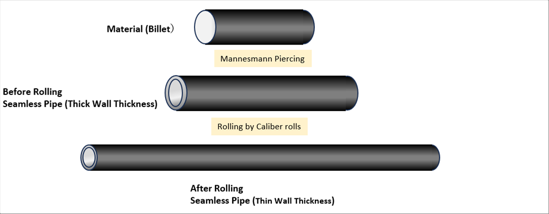
| The material of the pipes rolling is the round billet. The first one of the following pictures is the billet. The billet is pierced to the thick and short pipes in the piercing process. Then, the pipe is rolled to the thinner one. |
| |
 |
| |
| The Mannesmann Piercing method is used for the Piering process. (Please see the Mannesmann Piercing for the piercing process.) |
| |
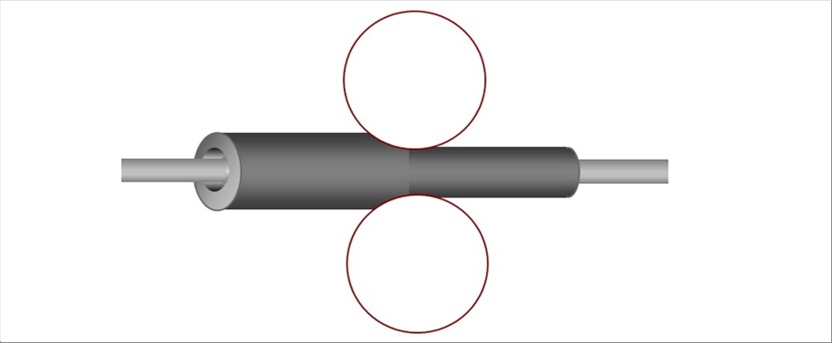
| The pipe rolling process is applied from the "Before" one to the "After" one. In addition to a pair of the caliber rolls, a bar is necessary in between the caliber rolls . |
| |
| The rolling process of the pipe rolling is same as the plate one. |
| |
 |
| |
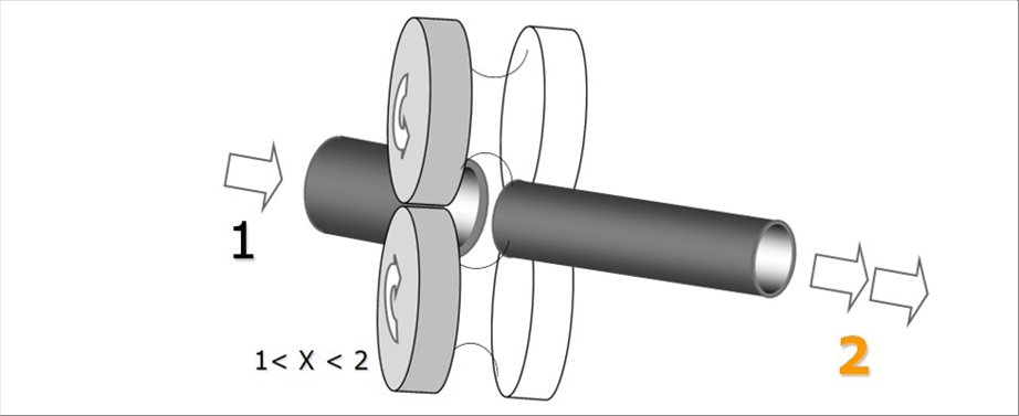
| In order to have a better understanding. I would omit drawing the bar. The pipes rolling is as following. |
| |
 |
| |
| Same as the plate rolling, the roll speed should be between one (1) and two(2). |
| |
 |
| 3 Multiple numbers of Pairs of Rolls |
| |
| Let7s consider the two (2) or more pairs of the rolls. |
| |
| A pair is called a stand. So, two (2) pairs of rolls are two (2) stands. As you may agree, one (1) stand has a limitation of the maximum thickness reduction due to many reasons. Therefore, in order to perform a big reduction in wall thickness, it is necessary to use multiple stands. The condition is common to both of the plates rolling and seamless pipes one. |
| |
| The following picture shows the plate rolling with four (4) stands. The roll stands are arranged horizontally, and the roll gap of the next stand is set smaller stand by stand. |
| |
 |
| |
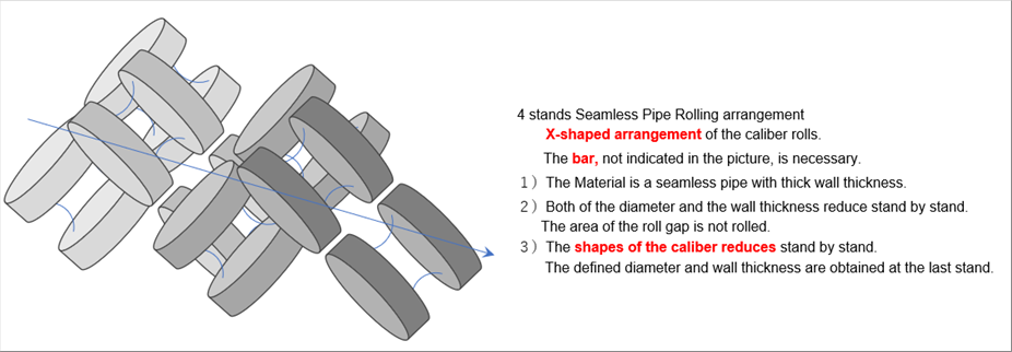
| The next figure indicates the seamless pipe rolling. The bar, which is necessary, is not shown. Different from the above plate rolling, the area of the roll gaps cannot be rolled. The no-rolled area is rolled at the next stand. |
| |
 |
| |
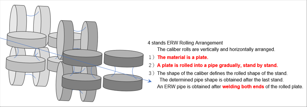
| Pipes are produced from the plates. One of the method is the ERW. It rolls a plate into a tube. The caliber rolls are vertically and horizontally arranged. The process does not reduce the wall thickness of the plate, and therefore, I would omit it. |
| |
 |
| |
| |
| When we think about the roll speed control of adjustment of three (3) or more stands, we canconsider the first and second ones, and then we can continue to the third one, then ane after another. Therefore, the two (2) stands case is enough for us to consider. |
| |
| As seen above, the seamless pipes rolling stands are arranged in a X-shape, ninty (90) degrees rotatioin to each other. Therefore, it is hard to draw the cross section. Then, we assume that the pipes rotates 90 degrees at each stand and the rolles are arranged in the same direction. |
| |
| The left picture shows the plate rolling, and the right is the seamless pipes one. The is a bar, which penetrates trough the all stands, the pipe is rolled between the rolls and the bar. |
| |
 |
| |
| During the seamless pipes rolling, the friction and the speed of the bar do affect the rolling condition; however, if we focus on the wall thickness change, both of the plate rolling and seamless pipes one are similar. The picture of the plate rolling is used in the rest of the article. To start with, let's consider that the rolling are conducted in the smooth way, it might be due to by chance. |
| |
 |
| - Adjusting Method for Thinner Wall Thickness |
| |
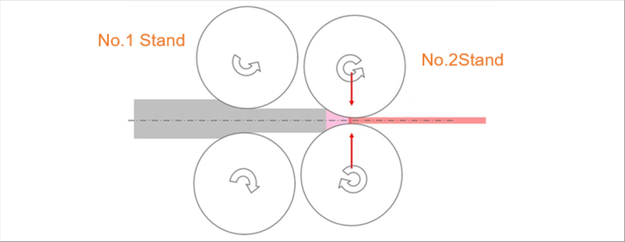
| The roll gap of the no.2 stand is squeezed in order to obtain the thinner wall thickness. |
| |
 |
| |
| The roll gap of the no.2 stand became smaller, and therefore, the outgoing wall thickness of the no.2 stand (in red) becomes smaller. The rotational speed of the no.1 stand keeps same, it means that the plate (seamless pipe) speed of the no.1 stand does not change. Now the speed condition of the no.2 stand becomes clear. It is that the same incoming speed and the faster outgoing one. As explained before, it is necessary to rotate faster in the no.2 stand, which is roughly same as the speed increase of the outgoing one. |
| |
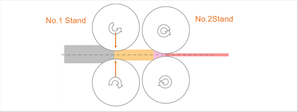
| Then, we keep the same gap of the no.2 stand and let's squeeze the no.1 stand roll gap. Let's see which part changes. |
| |
 |
| |
| The speed of the orange colored area becomes faster when we squeeze the roll gap of the no.2 stand. The area is the outgoing plate of the no.1 stand as well as the incoming material to the no.2 stand. Therefore, it affects the roll speeds of both of the stands. It is necessary to rotated the both stand faster. We know that the speed increases of both stands are roughly same as the one of the orange area. |
| |
 |
| - Adjusting Method for Thicker Wall Thickness |
| |
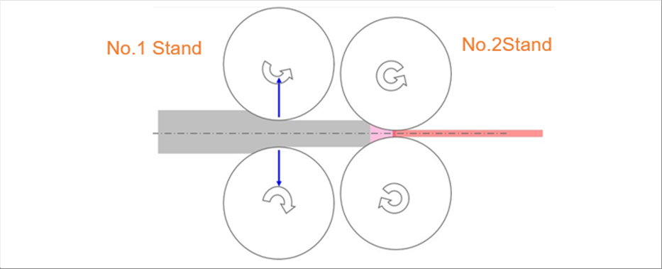
| The wall thickness becomes thicker when you open the roll gaps. Let's consider how to control the roll sped of the case. |
| |
 |
| |
| As an example, let's open the gap to close to the original one. When we open the no.1 stand roll gap, the wall thickness reduction of the stand becomes smaller, and the outgoing wall thickness of the no.1 stand becomes thicker. Therefore, the outgoing plate (seamless pipe) speed of no.1 stand becomes slower. Please note that the outgoing of the no.1 stand is the incoming to the no.2 stand. We need to reduce the roll rotating speed of both stands. |
| |
| |
| Author: T. Oda |
| Preparation in Excel, automatic html / css generation by the "excel2web". |


